Products
Centerway steel specializes in the production of the stainless steel pipe and fittings, and large inventory of resources, Factory direct sales

Centerway steel specializes in the production of the stainless steel pipe and fittings, and large inventory of resources, Factory direct sales

Stainless Steel Flanges Specifications:ASTM A182 / ASME SA182
Size:1/2″(15 NB) to 48″
Standards:ANSI/ASME B16.5, B 16.47 Series A & B, B16.48, BS4504, BS 10, EN-1092, DIN, etc.
Class / Pressure rating:150#, 300#, 600#, 900#, 1500#, 2500#, PN6, PN10, PN16, PN25, PN40, PN64 etc.
ASTM A182 for alloy and stainless welding neck flange. Alloy for F11, F22, stainless for F304/F304L, F316/F316L
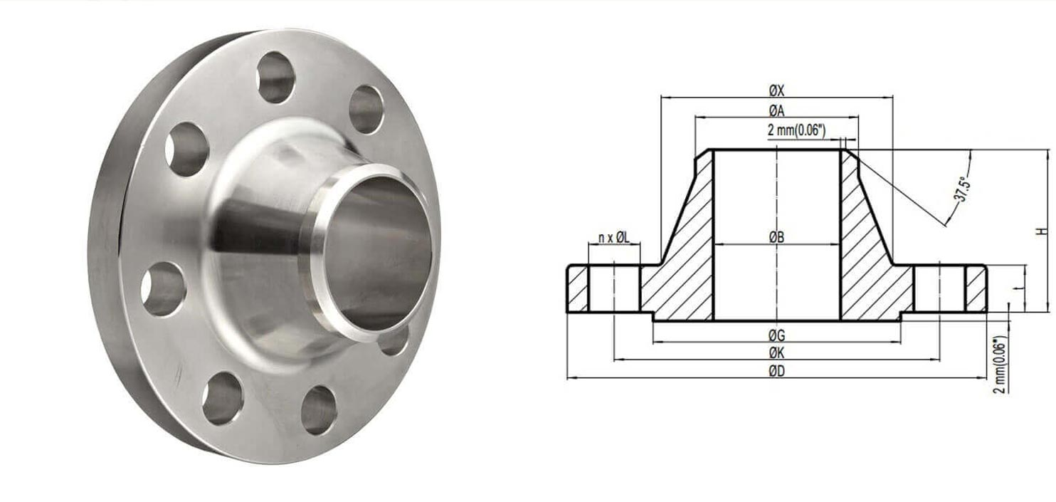
The Welding neck flanges is normally referred to as the high hub flange. It is designed to transfer stresses to the pipe, thereby reducing high stress concentrations at the base of the flange.
It is compatible to the pipelines that works in high or low temperature and bear high pressure. Specially for the pipe or the valves when PN is larger than 2.5 Mpa.

Weld neck flange datasheets
|
Class |
Flat Face |
Raised Face |
Ring Type Joint |
|
ANSI 150 |
WN Flange ANSI 150 FF (in) |
WN Flange ANSI 150 RF (in) |
WN Flange ANSI 150 RTJ (in) |
|
ANSI 300 |
WN Flange ANSI 300 FF (in) |
WN Flange ANSI 300 RF (in) |
WN Flange ANSI 300 RTJ (in) |
|
ANSI 400 |
WN Flange ANSI 400 FF (in) |
WN Flange ANSI 400 RF (in) |
WN Flange ANSI 400 RTJ (in) |
|
ANSI 600 |
WN Flange ANSI 600 FF (in) |
WN Flange ANSI 600 RF (in) |
WN Flange ANSI 600 RTJ (in) |
|
ANSI 900 |
WN Flange ANSI 900 FF (in) |
WN Flange ANSI 900 RF (in) |
WN Flange ANSI 900 RTJ (in) |
|
ANSI 1500 |
WN Flange ANSI 1500 FF (in) |
WN Flange ANSI 1500 RF (in) |
WN Flange ANSI 1500 RTJ (in) |
|
ANSI 2500 |
WN Flange ANSI 2500 FF (in) |
WN Flange ANSI 2500 RF (in) |
WN Flange ANSI 2500 RTJ (in) |
The datasheets we have on this site are shown below. For simplicity sake, only datasheets that adhere to B16.5 are shown. ASME B16.5 covers flange dimensions from½”to 24”. For sizes larger than this, please visit our flange datasheets page.
Weld-Neck Tolerances
|
Dimensions |
Class |
Tolerances |
||
|
inches |
mm |
|||
|
D |
Outside Diameter* |
D ≤ 610mm/OD ≤ 24″ |
± 0.06″ |
± 1.60mm |
|
D > 610mm/OD > 24″ |
± 0.12″ |
± 3.20mm |
||
|
j |
Inside Diameter |
NPS ≤ 10″ |
± 0.03″ |
± 0.80mm |
|
12″ ≤ NPS ≤ 18″ |
± 0.06″ |
± 1.60mm |
||
|
NPS ≥ 20″ |
+ 0.12″, – 0.06″ |
+ 3.20mm, – 0.06mm |
||
|
g |
Diameter of Contact Face |
1.60mm (0.06″) Raised Face |
± 0.03″ |
± 0.80mm |
|
6.40mm (0.25″) Raised Face |
± 0.02″ |
± 0.50mm |
||
|
m |
Outside Diameter of Hub at base * |
m ≤ 610mm (24″) |
± 0.06″ |
+ 1.60mm |
|
m > 610mm (24″) |
± 0.12″ |
+ 3.20mm |
||
|
a |
Diameter of Hub at point of Welding |
NPS ≤ 5″ |
+ 0.09″, – 0.03″ |
+ 2.40mm, – 0.80mm |
|
NPS ≥ 6″ |
+ 0.16″, – 0.03″ |
+ 4.00mm, – 0.80mm |
||
|
k |
Bolt Circle Diameter |
|
± 0.06″ |
± 1.60mm |
|
|
Center to center of adjacent bolt holes |
|
± 0.03″ |
± 0.80mm |
|
|
Eccentricity between bolt circle diameter and machined facing diameters. |
NPS ≤ 2 1/2″ |
± 0.03″ |
± 0.80mm |
|
NPS ≥ 3″ |
± 0.06″ |
± 1.60mm |
||
|
l |
Drilling * |
|
± 0.03″ |
± 0.80mm |
|
h |
Overall Length through Hub |
NPS ≤ 4″ |
± 0.06″ |
± 1.60mm |
|
5″ ≤ NPS ≤ 10″ |
+ 0.06″, – 0.12″ |
+ 1.60mm, – 3.20mm |
||
|
NPS ≥ 12″ |
+ 0.12″, – 0.18″ |
+ 3.20mm, – 4.80mm |
||
|
b |
Thickness |
NPS ≤ 18″ |
+ 0.12″, – 0″ |
+ 3.20mm, – 0.0mm |
|
NPS ≥ 20″ |
+ 0.19″, – 0″ |
+ 4.80mm, – 0.0mm |
||
Equivalent Grades
|
STANDARD |
WERKSTOFF NR. |
UNS |
JIS |
BS |
GOST |
AFNOR |
EN |
|
SS 304 |
1.4301 |
S30400 |
SUS 304 |
304S31 |
08Х18Н10 |
Z7CN18‐09 |
X5CrNi18-10 |
|
SS 316 |
1.4401 |
S31600 |
SUS 316 |
316S31 |
- |
Z7CND17‐11‐02 |
X5CrNiMo17-12-2 |
Chemical Composition
|
Grade |
C |
Mn |
Si |
P |
S |
Cr |
Mo |
Ni |
N |
|
SS 304 |
0.08 max |
2 max |
0.75 max |
0.040 max |
0.030 max |
18 – 20 |
– |
8 – 11 |
|
|
SS 316 |
0.08 max |
2 max |
0.75 max |
0.045 max |
0.030 max |
16 – 18 |
2 – 3 |
10 – 14 |
0.1 max |
Mechanical & Physical Properties
|
Density |
Melting Point |
Tensile Strength |
Yield Strength (0.2%Offset) |
Elongation |
|
8.0 g/cm3 |
1400 °C (2550 °F) |
Psi – 75000 , MPa – 515 |
Psi – 30000 , MPa – 205 |
35 % |